

Copy and paste the code below into your blog post or website
Copy URL
Embed into WordPress (learn more)


Comments
comments powered by DisqusPresentation Slides & Transcript
Presentation Slides & Transcript
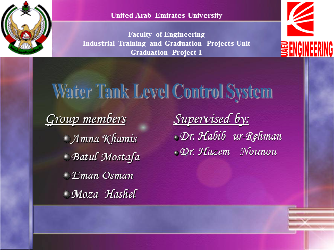
Supervised by:
Dr. Habib ur-Rehman
Dr. Hazem Nounou
United Arab Emirates University
Faculty of Engineering
Industrial Training and Graduation Projects Unit
Graduation Project I
Water Tank Level Control System
Group members
Amna Khamis
Batul Mostafa
Eman Osman
Moza Hashel
Overview
Tasks done through this semester.
Budget Estimate.
The project Environmental Impact.
Conclusion.
Tasks done
Gantt Chart of the above mentioned tasks.
Idea of the project:
Scope of the project.
Project description.
Design of the project:
Design methodology.
Hardware designing:
Project specifications
Control designing:
Simple case study.
Type of controllers.
Control techniques.
Software techniques implementation
Gantt chart
Searching Literature
Project background
MATLAB/SIMULINK
Linearization by MATLAB
Checking feasibility
Design system layout
Investigate control techniques
Generate MATLAB code for control techniques
Combining results
Preparing final presentation
Preparing final report
Ordering equipments
Scope of Project
The project focuses on enhancing the student's experiences in the following fields:
Product development.
Design and construction.
Computer modeling and analysis.
Testing and experimental investigations.
The System Layout and Description
Design Methodologies
A controller will be designed and simulated using MATLAB/Simulink software.
A prototype of the Water Tank System will be built.
The prototype will be interfaced to the computer via dSPACE (digital-Signal-Processor-Based) control board.
Project specifications
It is supposed to build a middle sized prototype.
Searching for Equipment:
Devices: pumps, tanks, hoses and sensors.
Software package: Simulink/MATLAB.
Interfacing board: dSPACE.
Pumps
The quantity of water to be handled is approximately three liters. This yields to get small pumps.
Pressure and frictional losses are negligible due to the size of layout and the nature of the used liquid (water).
High-speed centrifugal (rotary pumps) are preferred due to direct coupling to the internal motor.
Corrosion factor is negligible due to the layout nature.
Pumps
Hoses
Volume of tanks and power of used pumps are essential factors for choosing hoses.
Hoses should be as smooth as possible to avoid friction which leads to slow down the flow rate of water.
Flexibility and ability of connecting chosen hoses to other components should be taken into consideration.
Hoses’ length must be compatible with the system layout.
Hoses
Tanks
Capacity of tanks should be chosen so that three liters of water are accommodated.
Tanks should be of light materials (i.e: plastic) in order to be portable and easy to move.
Tanks should be transparence in order to notice the water level.
Also, they should be covered to avoid any disturbances that come from outside.
Tanks
Sensors
Pressure of water and tanks’ specifications, such as volume and height, should be considered while choosing sensors.
Volume of sensors must be compatible with the system layout.
Sensitivity of sensors has to be as high as possible.
Sensors
MATLAB / Simulink
The dSpace Board
Case Study (Process Control)
The case study introduced the simple control concepts to be generalized to our project. They are:
Linearization.
Types of controllers.
Process control experiment.
Linearization and control concepts
All real systems are non-linear.
Linearization is a method at which non-linear system is converted to linear systems to simplify dealing with systems.
Simple experiment of a temperature control system
Design of a simple experiment by MATLAB/Simulink.
Controlling temperature by ON-OFF controller.
MATLAB/Simulink model of the Temperature Experiment
Resultant temperature
ON-OFF Controller
Simplest control method.
Easy to be developed.
Effective for most disturbances.
Drawback: uses a lot of energy.
PI Controller
PI stands for Proportional-Integral Control.
It depends on two parameters:
Proportional gain (Kp).
Integral gain (KI).
Easy to be developed.
Consumes less energy than ON-OFF controller.
State variable feedback
When the control signal for the process is a direct function of all the state variables.
Fuzzy Controller
An intelligent and complicated controller.
Will be studied later according to the availability of time.
Control Techniques
A system was used from a reference book to apply the following techniques.
The technique implemented are:
Regulation:
With observer.
Without observer.
Tracking:
With observer.
Without observer.
Regulation with observer
X’ = AX + BU,
noting that X is the state to be estimated
Y = CX,
Y is the output desired from the system described in these equations
Here we are assuming having a new equation for the error. This error gives a value that describes how far we are from the desired state variable value.
Depending on the following set of equations:
E = X – X^, E represents the error
E’ = (A-LC) E L is a matrix form factor that appears in the X^ equation
as:
X^ = AX + BU + L(Y-Y^)
The goal here is to choose the following parameters with accordance to the following constrains:
Select K such that (A-BK < 0)
Select L such that (A-LC < 0)
Regulation with observer system
Regulation without observer
X’ = AX + BU,
noting that X is the state.
Y = CX,
Y is the output desired from the system described in these equations.
X’ = AX – BKX
as: U = -KX
Then:
X’ = (A-BK) X
select K such that (A-BK < 0)
Regulation without observer
Tracking without observer
X’ = AX + BU,
noting that X is the state to be estimated.
Y = CX,
Y is the output desired from the system described in these equations.
U = -KX + JR R is the desired trajectory.
After some algebraic steps, the closed loop system can be stated as:
X’ = Abar X+ Bbar R
Y = Cbar X + Dbar U
Where:
Abar = A- BK
Bbar = BJ
Cbar = C and Dbar = 0.
Tracking without observer system
Tracking with observer system
X’ = AX + BU X is the state
Y = CX Y is the output
U = -KX + JR R is the desired trajectory.
The closed-loop system is:
Tracking with observer
The generated MATLAB code is available in the Appendix if needed.
Budget Estimation
Some descriptive pictures for the components used in the prototype are shown in this Appendix
Environmental Impact
Control the level of any liquid in any container.
Example: Chemical industrial environment used in factories that pack drinks or medicines.
The designed control system has almost no bad effect on the environment, except if the subjects remaining of building the prototype are to be thrown in the environment.
Conclusion
Software experience is to be gained throughout working on this project on different scales.
Working in team, organizing project timings and dealing with products are essentials for good engineer. Hopefully, they will be well-covered.
Learned Ethics and lessons.
Any Questions Please
Regulation without observer
A=[1 1 -1;4 3 0;-2 1 10];
B=[0;0;1];
n=length(B);
p=[-2 -3 -1];
k=place(A,B,p);
Abar=A-B*k;
t=0:0.1:10;
D=[0];
u=0*ones(1,length(t));
C=[1 0 0];
sys=ss(Abar,zeros(n,1),C,D);
lsim(sys,u,t,[1,2,3])
hold on
C=[0 1 0];
sys=ss(Abar,zeros(n,1),C,D);
lsim(sys,u,t,[1,2,3])
C=[0 0 1];
sys=ss(Abar,zeros(n,1),C,D);
lsim(sys,u,t,[1,2,3])
Regulation with observer
A = [-2 -2.5 -0.5; 1 0 0; 0 1 0];
B = [1; 2; 3];
C = [1 4 3.5];
D = [0];
[n,n]=size(A);
p = [-3 -5 -7];
Lt= place(A',C',p);
L = Lt';
K=place(A,B,p);
Abar = [A -B*K ; L*C A-B*K-L*C];
t=0:0.1:2.5;
u=0*ones(1,length(t));
figure
sys3=ss(Abar,ones(2*n,1),[1 0 0 0 0 0],[0]);
lsim(sys3,u,t,[1,2,3,1,2,3])
hold on
sys3=ss(Abar,ones(2*n,1),[0 1 0 0 0 0],[0]);
lsim(sys3,u,t,[1,2,3,1,2,3])
hold on
sys3=ss(Abar,ones(2*n,1),[0 0 0 0 0 1],[0]);
lsim(sys3,u,t,[1,2,3,1,2,3])
title('Regulation with observer - states estimates')
sys3=ss(Abar,ones(2*n,1),[0 0 1 0 0 0],[0]);
lsim(sys3,u,t,[1,2,3,1,2,3])
title('Regulation with observer - actual states')
figure
sys3=ss(Abar,ones(2*n,1),[0 0 0 1 0 0],[0]);
lsim(sys3,u,t,[1,2,3,1,2,3])
hold on
sys3=ss(Abar,ones(2*n,1),[0 0 0 0 1 0],[0]);
lsim(sys3,u,t,[1,2,3,1,2,3])
Tracking without observer
A = [-2 -2.5 -0.5; 1 0 0; 0 1 0];
B = [1; 2; 3];
C = [1 4 3.5];
D = [0];
[n,n]=size(A);
p = [-3 -5 -7];
K=place(A,B,p);
Abar =A-B*K ;
Cbar=C;
Dbar=[0];
sysx=tf(ss(Abar,B,Cbar,Dbar));
J=1/dcgain(sysx);
Bbar=B*J;
t=0:0.1:7;
lt=length(t);
r=[1*ones(1,(lt-1)/2) 3*ones(1,((lt-1)/2)+1)];
figure
sys4=ss(Abar,Bbar,Cbar,Dbar);
lsim(sys4,r,t,[0.1,0.2,0.3])
Tracking with observer
A = [-2 -2.5 -0.5; 1 0 0; 0 1 0];
B = [1; 2; 3];
C = [1 4 3.5];
D = [0];
[n,n]=size(A);
p = [-3 -5 -7];
K=place(A,B,p);
Lt= place(A',C',p);
L = Lt';
Abar = [A -B*K ; L*C A-B*K-L*C];
Bbar=[B;B];
Cbar=[C 0 0 0];
Dbar=[0];
sysx=tf(ss(Abar,Bbar,Cbar,Dbar));
J=1/dcgain(sysx);
B2bar=Bbar*J;
t=0:0.1:7;
lt=length(t);
r=[1*ones(1,(lt-1)/2) 3*ones(1,((lt-1)/2)+1)];
figure
sys4=ss(Abar,B2bar,Cbar,Dbar);
lsim(sys4,r,t,[0.1;0.2;0.3;0.1;0.2;0.3])h
1.22 X 2.44 m2
P.V.C. sheet
Hose Fittings
Nipple ½”
Non-return Valve
Clamps ½”
Relays
Silicon Glue
PVC Glue
Tapes
Pipe wrench (Resemble adjustable spanner)
Drill
Drill, Hale Saw & Hale Saw bit
Hale Saw
Hale Saw bit
